Working with a LCD character display
In this tutorial you will learn how to hook up a HD44780-based LCD character display. This tutorial uses a 20 character by 4 line display, but most of these types of displays are hooked up the same and will work with the provided code.
Parts
LCD character display (HD44780-based)
Potentiometer
16 jumper wires
Wire the circuit
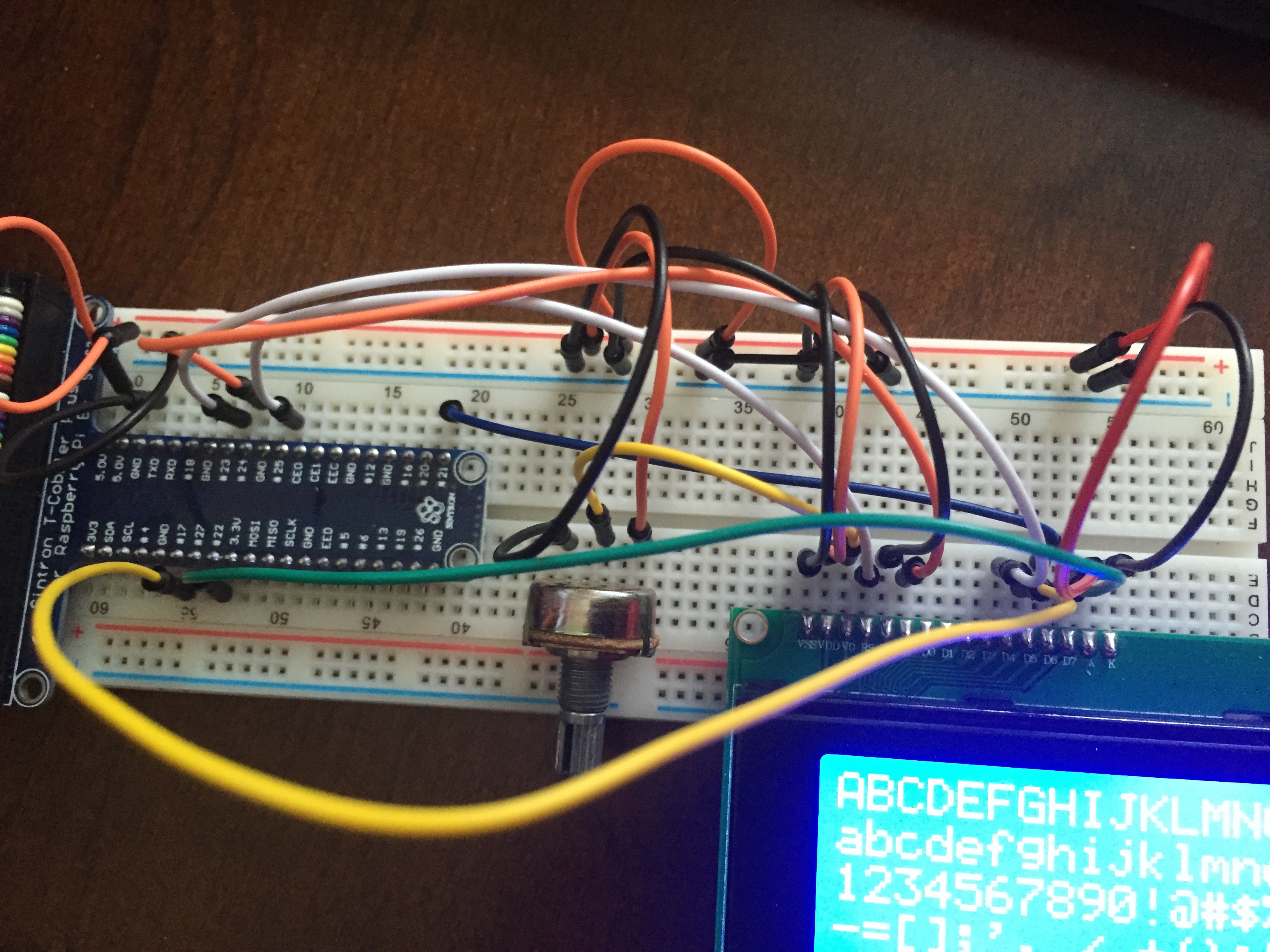
The LCD consists of 16 pins, of which 12 are used. The potentiometer is used to control the display's contrast. These are the overall steps: 1. Plug the LCD into your breadboard. Make sure you have plenty of space to work with. The pins must not overlap with any of the pins in the GPIO cobbler connector.
Wire up power and ground. The LCD uses 5v power. There are several power and ground connections so you'll want to use the power and ground rail on the side of the breadboard.
Connect the potentiometer. You can plug this in anywhere on the board with space.
Wire the LCD to the GPIO pins. The specific pins you use does not matter, but if you use different pins than described here, you'll need to update the code to use the pins you connected.
Wire the LCD to the potentiometer.
With this all hooked up, you should see the LCD light up and ought to be able to turn the potentiometer to adjust the contrast so that you can see the boxes where the characters are displayed. The LCD pins are numbered left to right when looking at the LCD with the pins at the top. These are the specific pin connections:
LCD Pin |
GPIO Pin |
|---|---|
#1 (GND) |
GND |
#2 (VCC) |
5.0v |
#3 (Vo) |
To potentiometer (see below) |
#4 (RS) |
#25 |
#5 (RW) |
GND |
#6 (EN) |
#24 |
#7, #8, #9, #10 |
Not used |
#11 (D4) |
#23 |
#12 (D5) |
#17 |
#13 (D6) |
#21 |
#14 (D7) |
#22 |
#15 (LED+) |
5.0v |
#16 (LED-) |
GND |
A potentiometer is used to adjust the contrast of the LCD. It is connected like this:
Pot Pin |
LCD Pin / GPIO Pin |
|---|---|
#1 |
GPIO GND |
#2 |
LCD #3 (Vo) |
#3 |
GPIO 5.0v |
When everything is connected correctly you will see the LCD light up and you'll be able to adjust the contrast with the potentiometer. You will not see any characters, although you ought to be able to see the individual character boxes.
Create the Xojo app
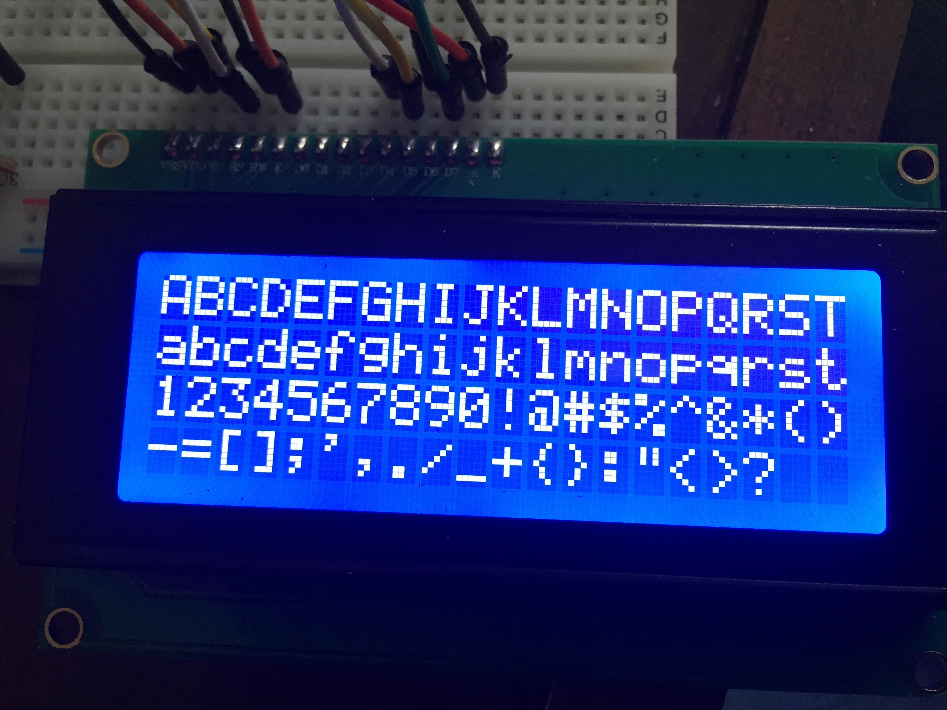
You'll use the Xojo GPIO library to display text on the LCD. This library has the GPIO.LCD module which contains methods you can call to easily initialize and display text on the LCD.
This code displays text on the LCD:
// Display text on 4-line LCD
GPIO.SetupGPIO

Const kRSPin = 25
Const kEPin = 24
Const kD4Pin = 23
Const kD5Pin = 17
Const kD6Pin = 21
Const kD7Pin = 22

Var lcd As New GPIO.LCD(kRSPin, kEPin, kD4Pin, kD5Pin, _
  kD6Pin, kD7Pin)

lcd.Clear
lcd.Home
lcd.SetMessage("ABCDEFGHIJKLMNOPQRSTUVWXYZ", 1)
lcd.SetMessage("abcdefghijklmnopqrstuvwxyz", 2)
lcd.SetMessage("1234567890!@#$%^&*()", 3)
lcd.SetMessage("-=[];',./_+{}:""<>?", 4)
This code displays and scrolls text on the LCD:
GPIO.SetupGPIO

Const kRSPin = 25
Const kEPin = 24
Const kD4Pin = 23
Const kD5Pin = 17
Const kD6Pin = 21
Const kD7Pin = 22

Var lcd As New GPIO.LCD(kRSPin, kEPin, kD4Pin, kD5Pin, _
  kD6Pin, kD7Pin)

lcd.Clear
lcd.Home
lcd.SetMessage("This text is scrolling to the right.", 1)
For i As Integer = 1 To 20
  lcd.ScrollDisplayRight
  App.DoEvents(300)
Next

lcd.SetMessage("This text is scrolling to the left.", 1)
For i As Integer = 1 To 20
  lcd.ScrollDisplayLeft
  App.DoEvents(300)
Next